APPARATUS FOR VERIFICATION OF BERNOULLI’S THEOREM
EXPERIMENTAL SET-UP

THEORY
Considering
friction less flow along a variable area duct, the law of conservation of
energy states “for an inviscid, incompressible, irrotational and steady flow
along a stream line the total energy (or head) remains the same”. This is
called Bernoulli’s equation

The total head of
flowing fluid consists of pressure head, velocity head and elevation head.
Hence
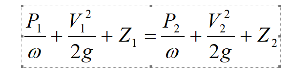
Where, P, V, and Z refer to the pressure, velocity and position of the liquid relative to some datum at any section.
|
Tube No. |
Distance from inlet
section (cm) |
Area of c/s of conduit A
(cm2) |
Velocity of flow (cm/sec) V= (Q/A) cm/sec
|
V2/2g (cm) |
 (cm) (cm) |
 (cm) |
|
1 |
7.5 |
14.67 |
|
|
|
|
|
2 |
15.0 |
13.33 |
|
|
|
|
|
3 |
22.5 |
12.0 |
|
|
|
|
|
4 |
30.0 |
10.67 |
|
|
|
|
|
5 |
37.5 |
9.33 |
|
|
|
|
|
6 |
45.0 |
8.0 |
|
|
|
|
|
7 |
52.5 |
9.33 |
|
|
|
|
|
8 |
60.0 |
10.67 |
|
|
|
|
|
9 |
67.5 |
12.0 |
|
|
|
|
|
10 |
75.0 |
13.33 |
|
|
|
|
|
11 |
82.5 |
14.67 |
|
|
|
|
RESULTS AND DISCUSSIONS:
1. If V is the velocity of flow at a
particular section of the duct and Q is the discharge, then by continuity
equation:

2. Calculate velocity head and total head.
3. Plot piezometric head (P/w + Z), velocity head (V2/
2g), total head (P/w + Z+ V2/2g)
v/s distance of piezometer tubes from same reference point.


No comments:
Post a Comment